
Establish the physical link
Identify the exact adapter and port, close competing software, confirm the transceiver direction control, and check A/B polarity against the device vendor’s naming—not just another vendor’s A/B labels.
- One continuous trunk with short stubs
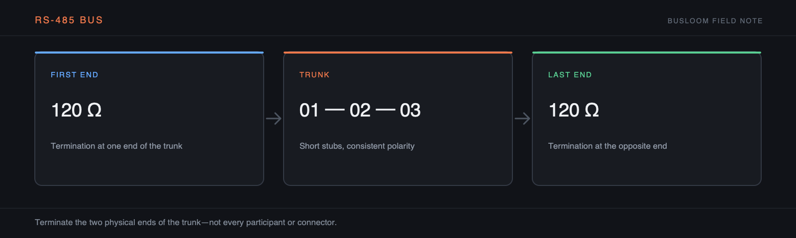
- Termination at the two physical ends
- Biasing in one controlled location
- A reference/common conductor where the installation requires it
Match framing before searching IDs
Baud rate, data bits, parity, and stop bits must match. If framing is wrong, probing 247 Unit IDs adds no information. Once framing is credible, probe a bounded Unit-ID set using one conservative function and address.
Read the evidence in order
No bytes suggests ownership, direction, wiring, ID, or device-state problems. Bad CRC suggests framing or signal integrity. A clean Modbus exception proves the physical and framing layers are working and moves the investigation up to function, address, or quantity.
Inspect topology, termination, and bias separately
RS-485 is intended as a bus, not an arbitrary star. Follow the cable route, identify both physical ends, note every stub, and confirm where termination is fitted. Too little termination permits reflections; too much loads the drivers. Bias establishes a known idle state but should not be added blindly at every node. Use the device and network documentation to understand which equipment already provides it.
Record conductor assignment rather than trusting A/B labels between vendors. Naming conventions vary. If polarity is uncertain, compare the terminal description or measured differential state with the manuals before swapping wires repeatedly.
Prove the adapter and workstation path
Confirm that the operating system exposes the expected serial port, no other process owns it, and the adapter supports the required framing. Note whether transmit direction is automatic or controlled by a driver. A loopback or bench test with one known device removes most of the site wiring and helps separate adapter behavior from network behavior.
Use a common reference or isolated interface according to the installation design. Shield connection, protective earth, signal reference, and isolation are related but not interchangeable. Ground potential problems can appear only after equipment is connected at both ends, so a device that works on the bench is not proof that the installed reference path is safe.
- Identify the exact USB–RS485 adapter and driver
- Confirm port ownership
- Verify automatic transmit direction
- Test one known server at a conservative baud rate
- Record the working framing before adding nodes
Create a baseline before increasing traffic
After the first valid response, record its raw frame, latency, and CRC result. Poll one stable register slowly and watch for errors before adding more sources. Then test the farthest node and the network under normal electrical load. A baseline makes later intermittent failures measurable instead of anecdotal.
If errors grow with traffic, inspect turnaround timing, duplicate Unit IDs, stubs, termination, and device processing capacity. If they correlate with power equipment switching, capture the event time and examine cable separation, shielding, reference, and adapter isolation. Change one variable at a time and keep the last known-good setup.