
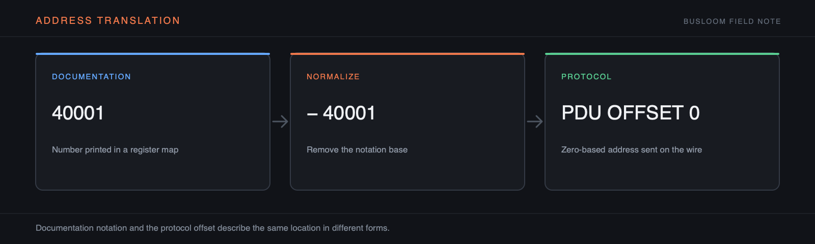
Separate the space from the number
Holding register 10 and input register 10 are different objects. FC03 selects holding registers; FC04 selects input registers. A client must know both the space and the PDU offset before it can form the request.
- 00001 commonly means coil PDU 0
- 10001 commonly means discrete input PDU 0
- 30001 commonly means input register PDU 0
- 40001 commonly means holding register PDU 0
Do not trust the prefix convention blindly
Some manuals number the first row 0, some 1, and some print a 3xxxx or 4xxxx label while still expecting the displayed number to be entered directly. Read the addressing note, inspect an example frame if supplied, or test a value with an unmistakable meaning.
If PDU 0 returns a clean value and PDU 1 returns another clean value, neither response proves the notation. Use a serial number, firmware revision, fixed nominal value, or a safe operating-point change to establish which row you actually read.
Prove the address before decoding
Keep the first read as an unsigned 16-bit raw value. Once the raw word matches the manual or a known device state, add width, signedness, byte/word order, scale, and unit. Changing all of those at once makes an off-by-one error look like an endianness problem.
Save both notations in the project. Busloom displays the documentation address for the person holding the manual and the PDU offset for the person reading the frame.
Check the full span, not only the first register
A tag that begins at the correct offset can still fail when it spans an invalid boundary. A 32-bit value starting at PDU 9 consumes registers 9 and 10; a 64-bit value consumes four registers. The requested quantity must cover the complete value, and the device must permit that complete range. An Exception 02 at a block boundary can therefore mean that the start is valid but the end is not.
When a large block fails, reduce it from the end until it succeeds. Then test the first rejected address separately. This distinguishes a real map boundary from a device-specific maximum request size. Keep these two limits separate in the project: one describes where data exists, the other describes how much the server accepts in one request.
Diagnose an off-by-one read with evidence
Choose a register whose value is recognizable without decoding tricks: a firmware version, fixed device type, nominal frequency, or counter that can be changed under controlled conditions. Read the documented candidate and the adjacent offsets as raw uint16 values. Record the exact function code and request bytes. The correct result is the one that agrees with both the manual and a second observation—not merely the most plausible decimal number.
Do not compensate for a bad address by changing scale, signedness, or word order. Those settings can make random words look credible and hide the original mistake. Resolve address space and PDU offset first, then width, then representation, and only then engineering scale and unit.
- Confirm the manual revision and table heading
- Write down the printed address exactly
- Derive one candidate PDU offset
- Inspect the request and raw response
- Repeat at a second known device state
Document the translation once
A reusable map should preserve the vendor notation and the wire notation side by side. Record whether the printed number was zero- or one-based, which function selects the space, how many registers the value occupies, and where that conclusion came from. A future reader should not have to reverse-engineer why documentation address 40017 became FC03 offset 16.
If the vendor publishes contradictory tables, keep a note with the tested firmware and the frame that proved the mapping. That evidence is more useful than silently correcting the number in a spreadsheet, because it tells the next engineer whether a later firmware revision needs to be rechecked.